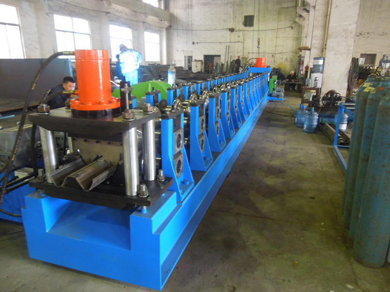
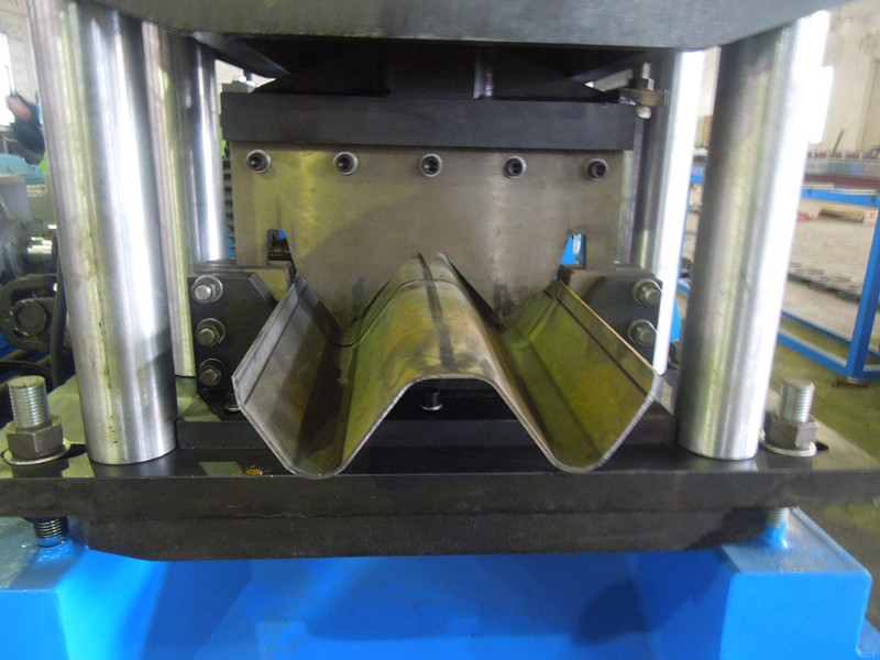
The highway Guardrail Roll Forming Machine can be designed as two or three wave profiles in one machine, you just need to add some stations at the end of the machine.
It mainly used for highway, largr parking areas, the scenic areas, provincial roads, rural roads and other anti-collision safety engineering construction.
Products structure concise, beautiful appearance and practical, easy to transport and install, hardly restricted by the terrain, has strong adaptability for the mountains, moderate cost, suitable for large-scale use.
Specifications:
Working process:
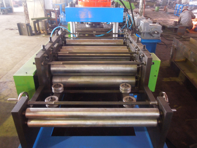
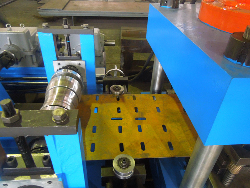
Decoiler - Feeding & Leveling machine - Punching - Main roll forming machine - PLC control system - Hydraulic cutting - Receiving table
Pictures for machine:
Training and Installation : Guardrail (Highway) Roll Forming Machine Guardrail (Highway) Roll Forming Machine,Steel Highway Roll Forming Machine,Guardrail Crest Tile Roll Forming Machine,Hydraulic Guardrail Roll Forming Machine,Guardrail Roll Forming Machine YingYee Machinery and Technology Service Co.,Ltd , https://www.yingyee.cn
At present, research at home and abroad mainly focuses on improving the torque capacity of the continuously variable transmission to increase its application range and improve the transmission efficiency of the continuously variable transmission. Therefore, the single chip can fully meet the system requirements and is inexpensive.
The input signal sensor required by the CVT has a throttle opening sensor, an engine speed, a master-slave pulley speed sensor, and the obtained signal is a data basis of a control ratio such as a speed ratio; the oil temperature oil pressure sensor is used to detect the hydraulic oil. Temperature and system pressure.
The actuators of the CVT are two linear proportional pressure valves that control the clamping force and speed ratio and two on-off valves that control the clutch and torque converter lock.
3 electronic control system hardware design system hardware can be divided into power module, input module, micro control system module, output module, communication module. The micro control system module is composed of a C164CI single chip microcomputer, a memory expansion circuit, an oscillation circuit, a clock circuit, and a reset circuit. The communication module mainly communicates with the host computer, that is, the C164 communicates with the PC through the serial interface. The design principles of the input and output modules are discussed below. 3.1 Input Module 3.1.1 Pulse Input Channel This system needs to detect the engine speed, CVT drive cone and driven cone speed, and use the easy-to-install magnetoelectric speed sensor for measurement. The output signal passes through the shaping circuit (see). Perform shaping to obtain a regular square wave signal. Then input to the pulse set input circuit capture comparison unit 2, and then through the interrupt service triggered by it to calculate the speed. In order to make full use of the internal resources of the C164, the system uses a combination of a low-speed normal external interrupt and an idle PEC interrupt, that is, the event captured by the capture unit triggers a normal external interrupt at a low speed; the PEC interrupt is triggered at a high speed.
This avoids the loss of pulses when idling, improving the CPU's response speed and data accuracy.
3.1.2 Analog input channel In this system, the engine throttle opening, CVT hydraulic oil system pressure and oil temperature signal should be measured in real time. These signals reflect the driver's operating intention and the running state of the continuously variable transmission. The necessary basis for real-time control of CVT. These analog quantities are filtered, amplified, and clipped, and then input to the A/D conversion channel of the C164CI.
3.1.3 Switching input channel The switching quantity detected in this system includes: gear selection signal, power/economic mode switching signal and braking signal. After passing through the voltage limiting circuit, these signals are input to the I/O port of the C164CI, and the status of the car is monitored by software inquiry to determine the working mode and driving state of the car. See the circuit diagram. 3.2 Output module The output module converts the control signal outputted by the single-chip microcomputer into the control quantity of the solenoid valve, and drives it to complete the corresponding operation. The speed ratio and clamping force control valve is a linear proportional valve. The input circuit of the oil-filled switch is proportional to the voltage applied to it. The operating voltage is ~12V. See the drive circuit. The output PWM signal of the single-chip microcomputer is shaped into DC by RC, then amplified by a non-inverting amplifier, and then amplified by a power driving tube.
Figure S Proportional M drive circuit The solenoid valve controlled by the clutch and the torque converter is a high-speed on-off valve, and the pressure change of the control object is realized by on-off and off. See the drive circuit. The I/O port of the C164CI controls the oscillation of the high-frequency oscillating circuit through the comparator, thereby controlling the composite transistor switch and turning on the solenoid valve coil power. The high-frequency oscillating circuit is used under the condition that the performance requirements of the solenoid valve are met, the power-on time is shortened, the power consumption of the solenoid valve is reduced, and the reliability of the system is improved.
4 Electronic Control System Software Design The software system of the electronic control unit is the core of the electronic control system. It combines the control law, control algorithm and the entire hardware system resources to realize the control function.
Software design, control system software components as shown. According to the modular design idea, the control software is divided into basic control module and interrupt control module.
Software structure. 1 system initialization block initializes the control registers and data registers of each peripheral of the CPU, sets the working mode of the counting/timer, initializes the input/output function of the I/O port and sets the initial value, initializes the serial communication port, and sets the high-speed capture. / Compare unit operation mode, initialize the watchdog timer (WatchDog), etc.
4.2 The data acquisition module uses the internal interrupt timing to collect the analog quantity and the switch quantity; the pulse signal is collected by the combination of the ordinary external interrupt and the PEC interrupt.
4.3 The data processing module processes the collected data and suppresses the interference signal by extremum discrimination and low-pass digital filtering.
4.4 Parameter calculation module uses the final result of data processing to calculate the required parameters, including engine speed, main/driven cone speed, throttle opening, system pressure and oil temperature, and actual speed ratio of CVT belt drive.
4. The S control decision block determines the current system state based on the system parameters obtained by the data acquisition module and the parameter calculation module, and adopts a corresponding control strategy. The control strategy corresponding to the CVT forward gear mainly includes the following aspects: The main function of the hydraulic torque converter for CVT is to improve the vehicle starting and stable low-speed driving, thereby enhancing the bad road passing, but the transmission efficiency is low. Therefore, when the vehicle speed is higher than a certain value, the torque converter is blocked. The author adopts a single-parameter control strategy with vehicle speed as the parameter to set the threshold values ​​of locked speed and unlocked speed (20km/h and 15km/h respectively). When the vehicle speed is higher than 20km/h, the hydraulic torque converter is controlled to be locked; when the vehicle speed is lower than 15km/h, the hydraulic torque converter is controlled to be unlocked.
The goal of the speed ratio control is to automatically change the speed ratio according to the operating conditions of the driver according to the operating conditions of the vehicle to maintain the engine at the ideal working point. The driver can choose between an economy mode and a power mode. Correspondingly, the CVT electronic control system will control the speed ratio change of the CVT to make the engine run on its economic characteristic curve or dynamic characteristic curve. To this end, a bench test was performed on a 1.3L engine matched to the CVT, and the universal characteristic curve of the engine was obtained as shown.
The engine universal characteristic graph obtains the optimal economic characteristic curve function by polynomial fitting = / (0 and the optimal dynamic curve function, = / p (a)., that is, the target speed of the engine under a certain throttle opening degree. , a is the throttle opening degree. The CVT electronic control system software first calculates the target speed of the engine according to the above fitting function, and then determines the target speed ratio according to the vehicle speed. In this system, the speed ratio is the control object, which is better. The digital PID controller is used for the control effect. See the control system block diagram.
Speed ​​ratio control system block diagram In this system, the clamping force of the metal strip is controlled by controlling the working pressure of the slave cylinder. Since the high-precision proportional valve is used as the pressure control actuator, an open loop control strategy is adopted.
First, according to a and \, the engine output torque 7 is determined by the engine data model, and then the target working pressure required by the slave cylinder is calculated and the magnitude of the proportional valve voltage V signal is determined accordingly. The control system block diagram is shown as 0.
12 is the test curve of the medium-speed ratio tracking effect of the gantry simulation car starting, accelerating and load changing conditions.
The two lines in the figure are the target speed ratio and the actual speed ratio respectively. The starting time CVT is in the neutral position, the metal belt transmission ratio is the maximum value. When the clutch is engaged, the vehicle starts and accelerates, and the actual speed ratio changes with the target speed ratio. Changes, as can be seen from the figure, the speed ratio tracking effect is good, basically fulfilling the expected requirements.
0 clamping force control system frame. The decision output module determines the control signals of the solenoid valves according to the decision result, mainly including the engagement and disengagement of the clutch, the lock/open of the torque converter, the speed ratio adjustment of the CVT, and the clamping force control.
4.7 Serial Communication Horizontal Block C164CI MCU provides asynchronous/synchronous serial interface (ASC0). This system adopts asynchronous communication working mode and sets the communication rate to %00bps. The data obtained by the data acquisition module is sent to the monitoring PC through serial communication. machine.
5 bench test verification In order to verify the correctness of the electronic control system, a bench test was carried out on the CVT test bench. 1 is the test block system block diagram, CVT test bench frame speed ratio tracking effect test curve
Matching material
Galvanized, PPGI, Aluminum
Material thickness range
1.5-3mm
Main motor power
18.5KW
Hydraulic motor power
15KW
Forming speed
8-10m/min(include punching)
Rollers
about 18
Material of rollers
45# steel with chromed
Shaft material and diameter
106mm, material is 40Cr
Way of driven
Chain transmission or Gear box
Material of cutter blade
Cr 12 mould steel with quenched treatment 58-62℃
Controlling system
Siemens PLC
Voltage
380V/3Phase/50Hz
Total weight
about 8 tons
Size of the machine
L*W*H 12m*1.5m*1.2m

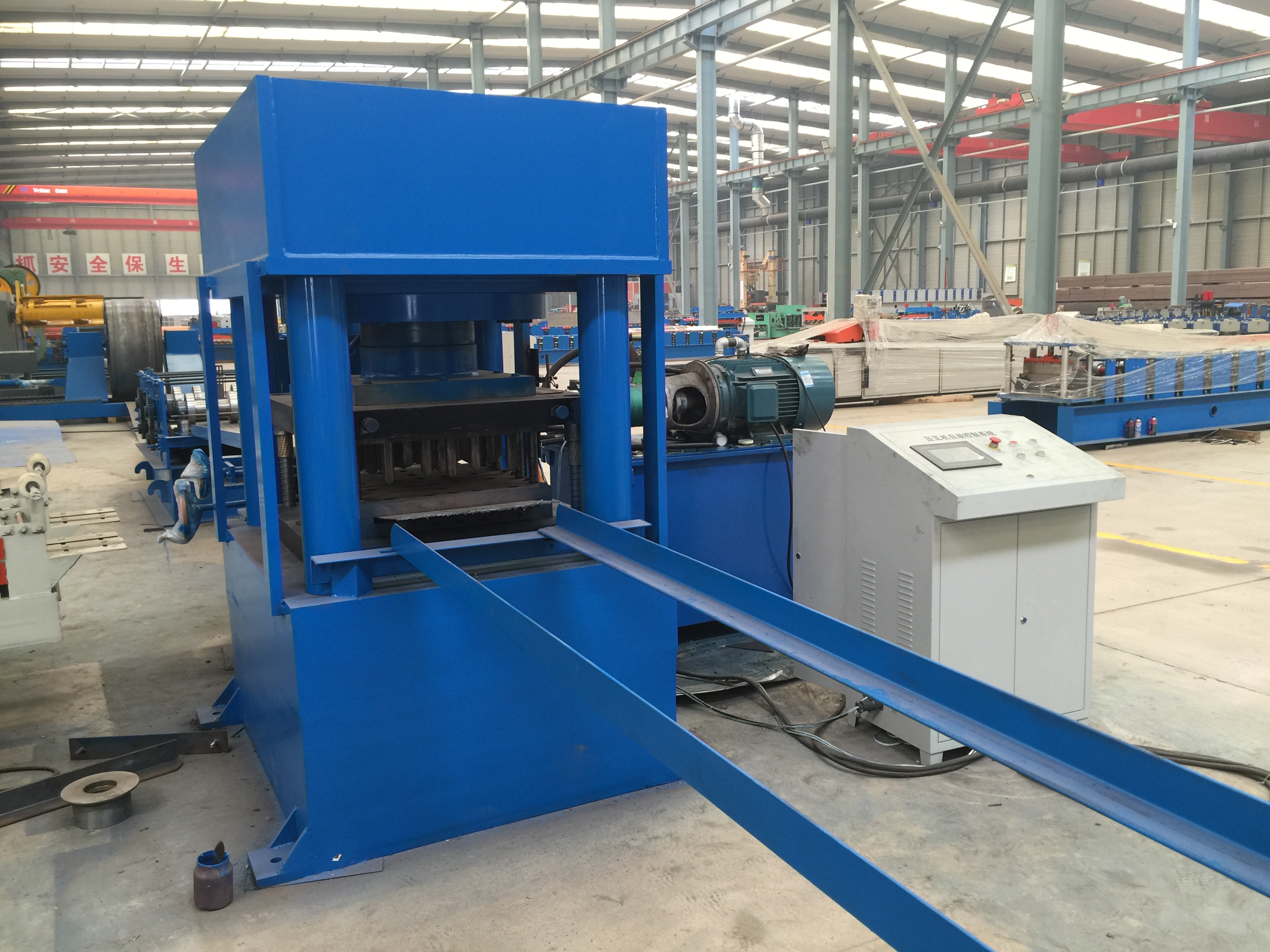
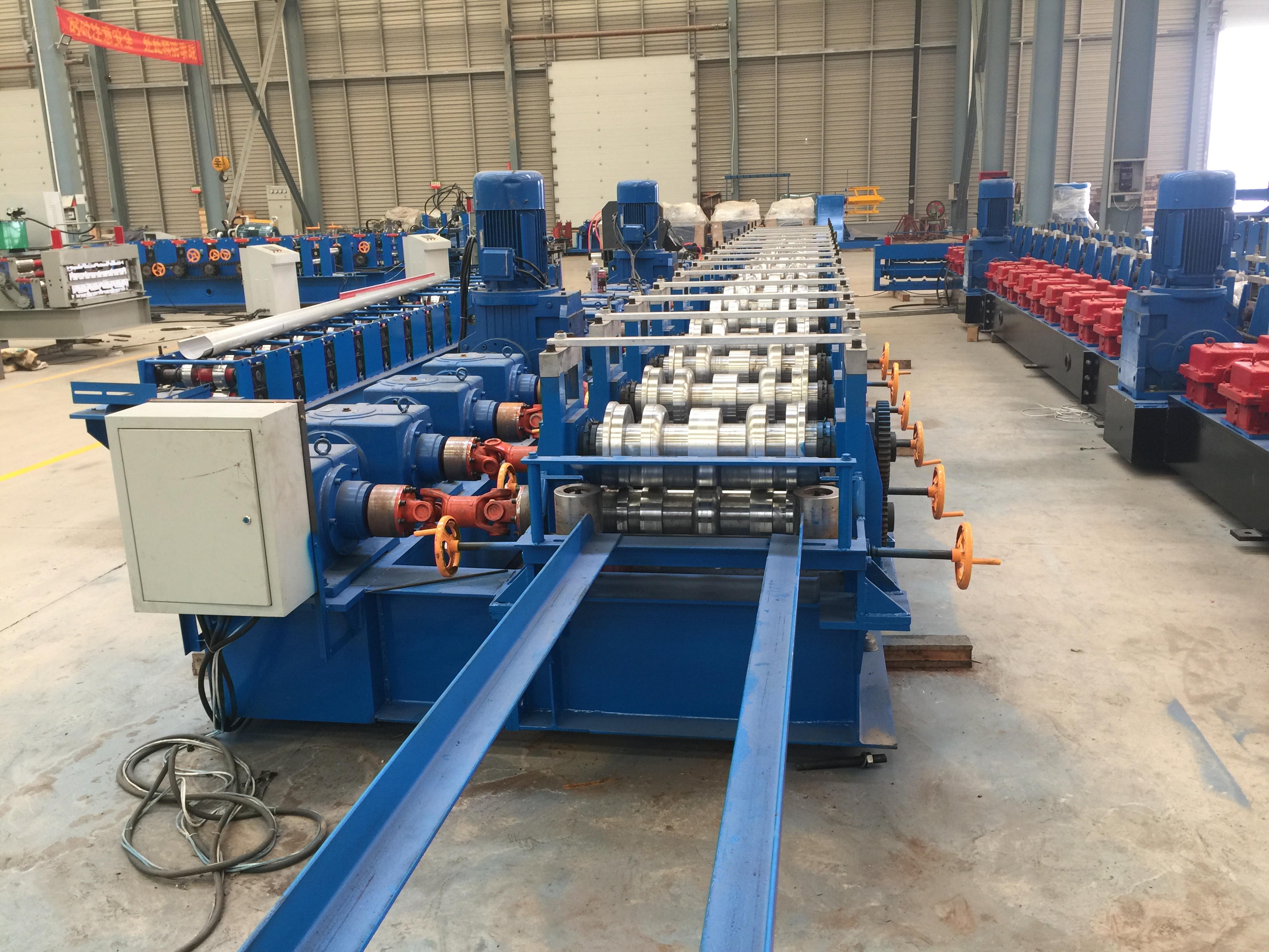
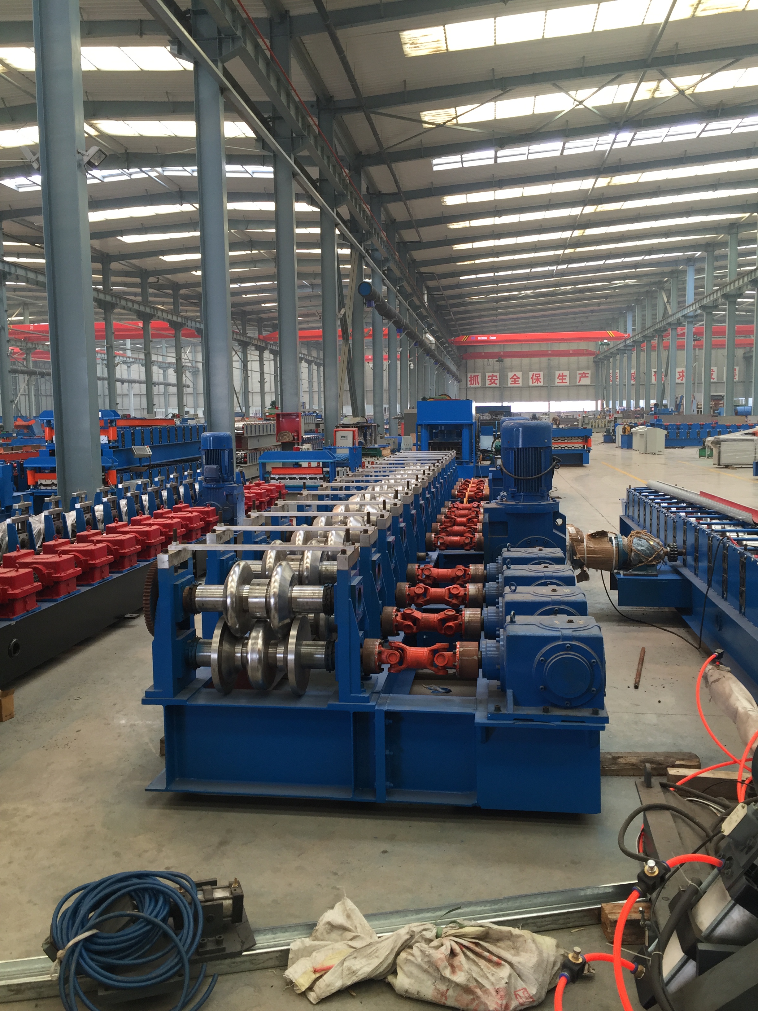
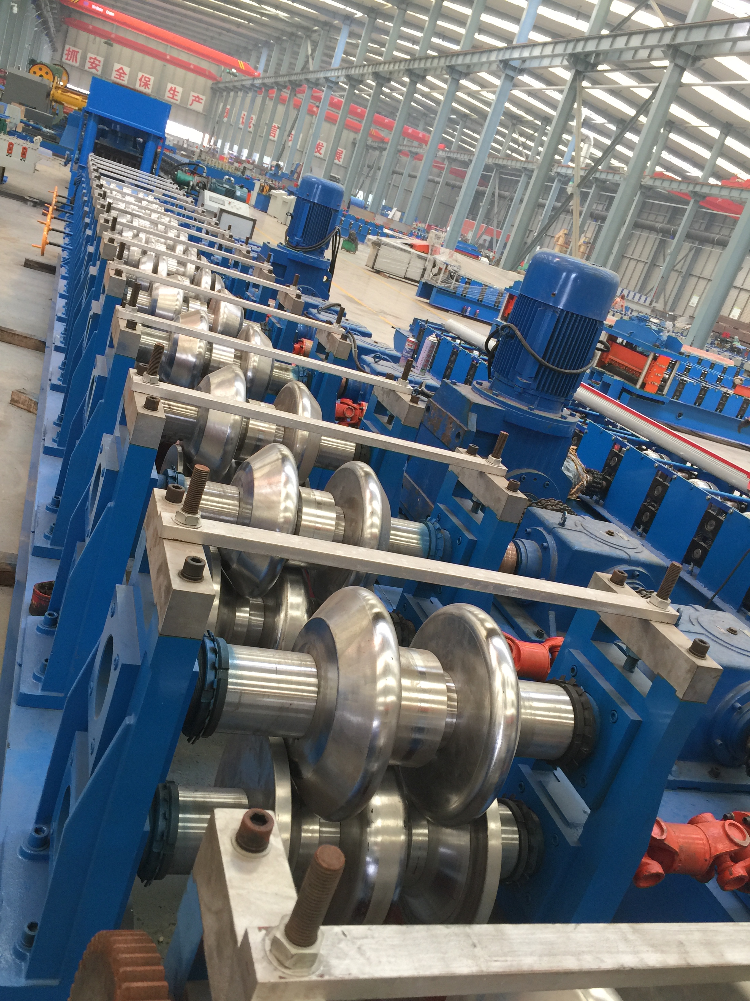
1. We offer installation service local in paid, reasonable charge.
2. QT test is welcome and professional.
3. manual and using guide is optional if no visiting and no installation.
Certification and after service:
1. Match the technology standard, ISO producing certification
2. CE certification
3. 12 months warranty since the delivery. Board.
Our advantage:
1. Short delivery period.
2. Effective communication
3. Interface customized.