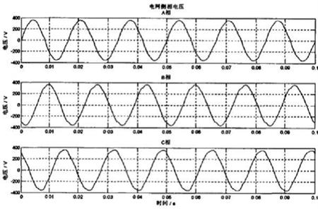
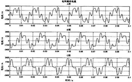
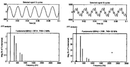
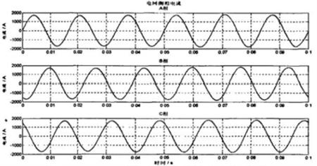
Xu Shuang Ankerui Electric Co., Ltd.     Jiading 201801 1 Introduction The ship integrated full-electric propulsion system is a comprehensive development of the two major systems of the current ship platform power and power , it is suitable for different types of ships . All countries in the world are conducting in-depth research on integrated electric propulsion systems for ships , and various types of integrated all-electric propulsion systems have been developed abroad and applied to multi-hull ships . According to statistics, since the late 1980s, developed the new passenger ships, icebreakers, ferries, about 30% have integrated all-electric propulsion system, and to fashion trends; the application of domestic civil ship in full electric propulsion has many forms: such as Jiangnan Shipyard of 3,200 tons all power abroad designed and built to promote chemical tankers, Shengli Oilfield "victory 232" was the project ship, China's 2006 hand over the first ship integrated full electric propulsion system of the train ro-ro ferry "China railway Bohai Sea Number One ." As a ship's main power system, the integrated all-electric propulsion system has become the main propulsion system favored by large-scale surface ships in the new century due to its high efficiency, high reliability, high automation, and low maintenance . The ship's integrated all-electric propulsion system includes: power generation, transmission, distribution, transformation, dragging, propulsion, energy storage, monitoring, and power management. The complexity of multi-function and multi-system also brings serious problems of harmonic pollution. . Whether each functional module of the integrated electric propulsion system is operating well and whether it is well coordinated with each other has a bearing on whether the entire integrated electric propulsion system can have good running conditions and excellent working performance. 2 Generation and Harm of Harmonics and Waveform Distortion 2.1 Harmonic sources The sources of harmonics generated in the integrated electric propulsion system are: 1) Advance the synchronous generator. The harmonic electromotive force generated by the advancing synchronous generator is caused by the non-sinusoidal distribution of the magnetic field in the air gap between the rotor and the stator. The magnetic fields in the air gaps under the magnetic poles of each pair of synchronous generators cannot be completely sinusoidally distributed, which is determined by the magnetic pole structure. Therefore, the electromotive force must contain harmonic components. 2) Transformer. The excitation circuit of the transformer has a nonlinear inductance. Therefore, the excitation current is a non-sinusoidal waveform, which causes the waveform of the current waveform to be distorted. In no-load conditions, the non-sinusoidal excitation current produces a voltage drop across the leakage reactance of the primary winding of the transformer, so that the transformer induced potential contains harmonic components. When the transformer is switched on without load, a large magnetizing inrush current often occurs. In severe cases, the inrush current waveform is strongly distorted. Not only can the amplitude be as high as tens of times the rated no-load current, but also the waveform of the positive and negative half-waves is extremely asymmetric. This inrush duration is relatively long and belongs to a quasi-stable non-sinusoidal wave. Characteristic harmonics are the main components of the waveform distortion generated by the rectifying device. Due to the high voltage level and large transmission power of the power transmission system, even a small percentage of harmonic components will cause non-negligible disturbance to the low-voltage equipment and weak equipment. 3) Frequency converter. The ship's integrated full-electric propulsion system adopts variable frequency speed control, and the harmonic frequency changes with frequency, which has a greater impact on the power quality of the ship's power grid. The harmonic component of the input current of the frequency conversion circuit is very complex, and its frequency is not only related to the input power frequency, the structure of the frequency conversion circuit, but also related to the output frequency of the frequency conversion circuit. In the above three harmonic sources, the synchronous generator is propelled into a harmonic voltage source, and the transformer is a harmonic current source. For harmonic current source devices, even if the voltage supplied to them is an ideal sine wave, the current they take will also contain harmonic components. The content of harmonics depends on their own characteristics and working conditions. After harmonic currents are injected into the ship's power grid, harmonic voltage drops on the impedance of the ship's power grid system will also cause waveform distortion at the voltages at various points in the power grid system. 2.2 Harmonic Harm Harmonics are one of the important factors affecting power quality. They are usually generated by nonlinear components in the power grid. Harmonics in the ship's power grid can have many adverse effects on the operation of the ship's equipment: 1) Reduce the efficiency of ship generators; 2) The phenomenon of overheating, vibration and noise in the electrical equipment, and the result of insulation aging, shortened service life, and even failure or burn-out; 3) Harmonics will also cause the reliability of the ship's relay protection and automatic control devices to decrease and cause malfunctions; 4) Harmonics can also cause serious interference to communication equipment and electronic equipment. Therefore, harmonics are a kind of electromagnetic environment pollution for the ship's power grid. Microelectronic devices are widely used in ship measurement, control, protection, and operation systems. They have high requirements for current waveforms and are susceptible to harmonic interference. The harmonics generated by the integrated full-electric propulsion system affect the instruments, instruments and equipment on the ship including the systems for measurement, protection, control, and operation through the ship's power grid. For example, the interference of harmonics on the computer mainly affects the accuracy and performance of magnetic components and data processing systems, thereby affecting the quality of computer-processed data. Harmonic effects on ship lighting and domestic electricity consumption are mainly reflected in increased losses, reduced life, and degraded operating performance. Harmonic problems have become increasingly prominent and serious. Major ship accidents caused by harmonics have occurred at home and abroad. In particular, due to the use of variable frequency drives, the motor insulation and the cable insulation layer are quickly aged or even burned; the common mode voltage induces a high shaft voltage on the motor shaft and forms a bearing discharge current to corrode the bearing, making the motor short-term. Scrapped; high frequency conductivity and radiated EMI reduce the reliability of the variable frequency drive system, increase the failure rate, and affect other electrical equipment on the power grid. Therefore, the study of the negative effects brought by the inverter and its solutions have important theoretical and practical values ​​in the electric propulsion system. 3 Harmonic Limit Analysis of Integrated Electric Propulsion System In order to solve the problem of harmonic pollution and low power factor generated by power electronic devices, the traditional method is to set up reactive power compensation capacitors and LC filters. These two methods are simple in structure and can both suppress harmonics and compensate reactive power. Has been widely used. However, the main disadvantage of this method is that the compensation characteristics are affected by the grid impedance and operating conditions, and it is easy to parallel resonance with the system. In addition, this compensation method has a large loss, and can only compensate for harmonics of a fixed frequency, and it is difficult to change the reactive power. Power and harmonics provide effective dynamic compensation. With the development of power systems, there is an increasing demand for fast dynamic compensation of reactive power and harmonics. The current trend is the use of power electronics for harmonic compensation, ie active power filters (APFs). 3.1 The advantages of active filters The main advantages of active filters are: (1) The active filter device is a high-impedance current source, and its access does not affect the system impedance. Therefore, such devices are suitable for serialized and large-scale production. (2) When the structure of the power grid changes, the device is not greatly affected by the impedance of the power grid , there is no danger of harmonics with the impedance of the power grid , and series-parallel resonance can also be suppressed. (3) In principle, it is more superior than PPF. The same device can simultaneously compensate multiple harmonic currents and non-rectified harmonic currents to complete the treatment of various harmonics. (4) To achieve dynamic compensation, it is possible to compensate harmonics with varying frequency and size and varying reactive power, and have extremely fast response speed to the changes of the compensation object. (5) Since the device itself can achieve output limitation, the active filter will not be overloaded when the harmonic current in the line suddenly increases, and it can function normally without disconnection from the system. (6) With a variety of compensation functions, reactive power and negative sequence can be compensated. (7) Harmonic compensation characteristics are not affected by changes in the grid frequency. (8) Centralized control of multiple harmonic sources. 3.2 ANAPF Series Active Power Filters Ankerui's ANAPF series active power filter device is a new type of power electronic device for dynamic suppression of harmonics and compensation of reactive power. It can compensate harmonics and varying reactive power that vary in size and frequency. Overcomes the shortcomings of traditional harmonic suppression and reactive power compensation methods such as LC filters and realizes dynamic tracking compensation. It is the best choice for harmonic control and reactive power compensation, and is a powerful guarantee for stable operation of offshore platform power systems. 3.2.1 How Does It Work? ANAPF series active power filter devices are connected to the power grid in parallel to detect the harmonic and reactive components of the load in real time. PWM inverter technology is used to generate one and current harmonic and reactive components from the converter. Corresponding inverse components are injected into the power system in real time to realize harmonic control and reactive power compensation. (see picture 1) Figure 1 ANAPF active power filter device schematic 3.2.2 Technical parameters Wiring Three-phase three-wire or three-phase four-wire Access voltage 3×380V ±10% Access frequency 50Hz ±2% Dynamic compensation response time Dynamic response <4ms, full response time <20ms; On-off level 10kHz Function settings Only harmonics are compensated, only reactive power is compensated, both harmonics are compensated and reactive power is compensated; manual and automatic switching are performed. Harmonic compensation times 2-21 times Type of protection DC over-voltage IGBT over-current device temperature protection Overload protection Automatic current limit in the set value, no overload occurs cooling method Smart air cooling noise < 65db (in the cabinet and operating in the rated state) Working temperature -10°C to +45°C Working environment humidity <85%RH non-condensing Installation occasion Indoor installation Altitude ≤1000m (for use at higher altitudes) Incoming and outgoing ways Down in and out Protection level IP21 Intelligent communication interface RS485/MODBUS-RTU Remote monitoring Optional Overall size (mm) (W×D×H) 30A 50A 75A 100A 600×500×1500 600×500×1500 600×500×1800 800×600×2200 Weight (kg) Three-phase four-wire Three-phase three-wire 30A, 50A 75A, 100A 30A, 50A 75A, 100A 280 360 240 290 3.2.3 Introduction to Function Modules u controller module APFMC-C100 Mainly by: DSP (digital signal processor), FPGA logic device, AD signal sampling circuit, DI / DO input and output control circuit, PWM waveform control circuit, RS485 communication circuit and other components, mainly used to complete the voltage and current signal acquisition And processing, instruction current calculation, switch circuit generation, PWM signal output, system external communication and system protection functions. The control system is the core of the active filter, which determines the main performance and indicators of the active power filter system. u converter module APFCOV Its core is the storage capacitor and IGBT module. The function of the converter is mainly to rectify the voltage of the grid through the IGBT power module to charge the energy storage capacitor, so that the bus voltage is maintained at a certain stable value. In this process, the converter works mainly in the rectification state, when the main circuit generates When compensating the current, the converter operates in the inverter state again. Considering that the product is operated in the power grid for a long time, the DC supporting capacitor adopts a thin film capacitor, and the power module adopts a German original product to ensure the quality of the entire machine. The choice of converter varies according to the size of the compensation current. u Reactor Modules APF-RE.DG, APF-RE.SDG The APF reactor acts as a filter to filter out unwanted harmonics from the grid generated by the APF. Reactors can be divided into single-phase and three-phase, currents from 15A to 200A and other specifications. uMan -machine interface APF-HMI When the APF cabinet is working, the system can monitor its network-side current, APF bridge arm current, and load-side current. The user can set the APF operation mode through the HMI. For the problems that occur during the operation, corresponding event records can be generated. HMI is a smart meter designed by our company for the power monitoring needs of power systems, industrial and mining companies, public utilities, and intelligent buildings. It uses a high-brightness TFT-LCD color display interface and implements parameter settings and controls through panel keys. Measurement of all power parameters, comprehensive energy metering and assessment management, and analysis of various power quality parameters. u matching current sampling transformer AKH-0.66-K 3.2.4 Technical advantages l DSP+FPGA digital control mode with extremely fast response time; l advanced main circuit topology and control algorithm, higher accuracy, more stable operation; l A machine with multiple functions, it can not only make up for harmonics, but also make up for reactive power. l Modular design, easy for production debugging; l Convenient parallel design to facilitate capacity expansion; l has a perfect bridge arm over-current protection; l Easy to use, easy to operate and maintain. 3.2.5 Active Filter Quotation and Component List Model Number: ANAPF100-400/B Reference price: 120,000 yuan/set The main product details: No. Name Model number Quantity 1 APF electrical cabinet 800X600X2200 1 2 Converter APFCOV-CVT100 1 3 Controller APFMC-C100 1 4 Reactor APF-RE.(S)DG-100 1 5 Active current transformer LT208-S7 3 6 filter DL-1TH1 2 7 breaker CVS160FTM160D4P3D 1 8 Contactor LC1D150M7C 1 9 MCB NDM1-63C32 1 10 Intermediate relay MY4NAC 2 11 R type transformer R320-0.38/0.22 1 12 Harmonic Detector ACR350EGH 1 13 wire 16mm 2 Some 14 wire 4mm 2 Some 4 Application examples of ANAPF active power filter This article takes the integrated electric propulsion system of an actual large-scale tourist passenger ship as an example. The basic parameters are as follows: The ship's power system is mainly divided into two parts: the 6600V medium voltage network and the 440V low voltage power network. The 4 main generators provide power for the main 6600V power grid. The main propulsion motors and thrusters are their main loads. The 440 main grid is connected to the 6600V power grid via a transformer. The loads include the main propulsion motor excitation system, steering gear, and hotel power service system. And other auxiliary equipment. When ANAPF is not put into the grid, the voltage and current on the grid side and the load side are exactly the same, so only the phase voltage and phase current on the grid side are listed below. Figures 2 and 3 show that there is almost no distortion of the phase voltage on the grid side when the ANAPF is not put into operation, but the waveform distortion of the phase current is very serious. The following is a Fourier analysis of phase A phase voltage and phase current on the grid side, respectively, to quantify the degree of distortion (3 cycles after 0.02 s as the object of Fourier analysis). Figure 2 Phase voltage waveforms on the grid side when ANAPF is not put into operation Figure 3 Waveform of the phase current on the grid side when ANAPF is not put into operation Fig. 4 A-phase voltage (left) and phase current waveforms and Fourier analysis on the grid side when ANAPF is not put into operation The Fourier analysis in Figure 4 shows that the phase voltage distortion is very small, the THD value is about 2.68%, and the THD value of the current is as high as 50.56%. The harmonic content is already high, and you can see 5 and 7 harmonics. The amplitudes of the waves are relatively large, which have been as high as 46% and 23% of the fundamental wave amplitude, respectively. Harmonic control measures are urgently needed to avoid affecting or even damaging other more sensitive loads. The compensated current command signal calculated by ANAPF will cancel each other because the compensation current and the harmonic current (and reactive current) amplitude are equal in phase and opposite each other, so that the grid current becomes a sinusoidal shape containing only the fundamental wave. Figure 5 and Figure 6 show the voltage and current waveforms of the ANAPF network after it is put into the power grid. Compared with the waveform diagrams (Figures 2 and 3) when the ANAPF is put into operation, it can be seen that the filtering effect is significant. The voltage and current waveforms after the ANAPF input are very close to the sine wave. . Figure 5 The phase voltage waveform of the grid after ANAPF is put into operation Figure 6 Waveform of the phase current of the grid side after the ANAPF is put into operation Figure 7 A-phase voltage (left) and phase current waveforms of the power grid after ANAPF input and its Fourier analysis The Fourier analysis of Figure 7 shows that the degree of distortion of the voltage and current on the grid side is reduced, especially the THD value of the current dropped from the previous 50.56% to the current 0.79%; the THD value of the voltage is now about 0.00% . The percentage of harmonic amplitude in the fundamental wave amplitude is less than 1.1%. Obviously, the harmonic voltage and harmonic current content on the grid side can meet the requirements of the relevant limit values. The above conclusions show that the Ankeray ANAPF series shunt active power filter device has a significant effect on improving the voltage and current on the grid side. 5 Conclusion At present, active filters have become the main development direction of power system harmonic pollution control. The ANAPF active power filter is an excellent solution that is particularly suitable for the harmonic suppression of the ship's power grid and is receiving widespread attention . Its use has better suppressed the harmonic pollution in the ship's power grid, greatly improved the power quality of the power grid, fully met the relevant requirements of the classification society, and will have broad prospects in the application of shipbuilding industry. references: [1] Feng Yinghua , Wu Wei , Yang Pingxi . Harmonic loss analysis and algorithm for main generator of integrated power system [J ]. Marine Engineering , 2008, 30 (5): 12 2 15. . [2] Qirong, Zhao Yuan, Chen industry APF - control structure principle [M] Beijing: Science Press, 2005.1-2, 20-25. [3] Song Yanqiong.Discussion on the Harmonic Suppression Scheme of Electric Power Propulsion Shipboard[J].Journal of Guangzhou Maritime College,2009,2(17): 11-14. [4] MA Xiaojun, CHEN Jianye, HAN Yingbiao, et al. Study on single-phase shunt active filter[J]. Journal of Tsinghua University: Natural Science, 1997, 37(7): 39-43. [5] Hu Ming, Chen Jun. Active Filtering Technology and Its Application [J]. Automation of Electric Power System, 2000, 24(3), 66-70. About the Author: Xu Shuang, female, undergraduate, Ankerui Electric Co., Ltd., the main research direction for the smart grid power distribution, Email: Mobile QQ "AAPF Active Power Filter Device Design and Application Atlas" (atlas number: ACR13CDX701) is edited by Ankerui Electric Co., Ltd. This atlas combines the characteristics of ANAPF active power filter device products, based on electrical design specifications, research Eliminating the problem of high-order harmonics in the power supply and distribution system to achieve the goal of improving the quality of power supply and ensuring the safe operation of the power system. The Atlas is applicable to the design and modification of harmonic suppression and comprehensive management of electrical equipment in industrial, civil, and public buildings in new construction, reconstruction, expansion, and technological transformation projects. If you need atlas, please provide your organization's name, department, address, zip code, contact person, contact telephone number, email address, fax 021-69155331, mail or QQ to Ankeru Xu cream engineer, Ankerui Electric will give you a free gift. . Large-Sized Casting Parts,Ebm 3D Printer Provider,Delicate Metal Castings,Delicate Metal Parts Guangdong Fenghua Zhuoli Technology Co., Ltd , https://www.fhzl3d-print.com


