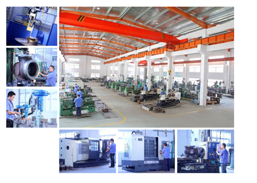
Railway Hydraulic Tamping Machine collecting end-users' experience at home and abroad, adopting new material and technology, this type of Tamping Machine is our upgrading product. lts basic structure and working principle reserves the original advantages, that is of double guide pillar frame and single cylinder lifting mode. Due to increasing the tine palm inserting depth and the guide pillar stroke stop means, it's able to to operate on II type concrete sleeper and II type concrete sleeper, and on various concrete sleeper and rail track. Tamping Machine,Railway Tamping Equipment,Turnout Tamping Machine,Hydraulic Railway Tamping Machine Shenyang Lubang Railway Maintenance Machinery Co.,Ltd. , https://www.srmfrailwayequip.com
Compact structure: small volume, light weight, easy maintenance
Smooth flow channel: low flow resistance, low pressure drop, high flow
Strong anti-wear performance: The ball is subject to hard alloy spray coating, and the seat sealing face is subject to hard alloy overlaying welding.
Fire-safe and antistatic: Meeting API607 requirements, it is provided with the antistatic device.
Main technical parameters
Type: two-piece type, three-piece type
Nominal diameter: DN15~600(NPS1/2~24)
Nominal pressure: PN1.6~10.0MPa(Class150~600)
Type of connection: flanged
Material: A216-WCB, A351-CF8, A351-CF8M, A351-CF3,
A351-CF3M, A217-WC6, A217-WC9
Bonnet: standard type: -29~250ºC
high temperature (cooling fin) type: 250~525ºC
low temperature (extension) type: -29~-20ºC, -196~-46ºC
See table 3 for working temperature and pressure ranges of various materials.
Packing: PTFE, flexible graphite, nickel-based wire reinforced flexible graphite
Plug type: O straight-through type
Plug material: A182-F304, A182-F316
Seat material: soft seal: PTFE, RPTFE, PPL
hard seal: A182-F304, A182-F316
Please see tables 3 for the material combination and surface treatment for body, plug, ball, seat, stem, etc.
Flow characteristic: quick opening
Rated Kv value: See table 4 for details.
Rated travel: 0~90ÐŽ
Seat Leakage class: soft seal: ANSI B16.104 class VI
Hard seal: ANSI B16.104 class V (hard seal class VI for special orders)
Nominal
PressureNominal diameter
Face-to-face
dimensionsFlange connection dimensions
RF Sealing surface
Opening
height(kg)
Reference
weight
NPS
DN
L
D
K
n-L
C
d
f1
H
Class
15011/2
40
165
125
98.4
4-16
15.9
73.0
2
630
42
2
50
178
150
120.7
4-18
17.5
92.1
2
640
45
21/2
65
190
180
139.7
4-18
20.7
104.8
2
690
55
3
80
203
190
152.4
4-18
22.3
127.0
2
750
68
4
100
229
230
190.5
8-18
22.3
157.2
2
780
80
5
125
254
255
215.9
8-22
22.3
185.7
2
850
110
6
150
267
280
241.3
8-22
23.9
215.9
2
940
130
8
200
292
345
298.5
8-22
27.0
269.9
2
1120
220
10
250
330
405
362.0
12-26
28.6
323.8
2
1330
270
12
300
356
485
431.8
12-26
30.2
381.0
2
1530
370
14
350
381
535
476.3
12-30
33.4
412.8
2
1710
510
16
400
406
595
539.8
16-30
35.0
469.9
2
1880
650
18
450
432
635
577.9
16-33
38.1
533.4
2
2160
1150
20
500
457
700
635.0
20-33
41.3
584.2
2
2360
1380
24
600
508
815
749.3
20-36
46.1
692.2
2
2660
1520
28
700
610
835
795.3
40-22
43.0
762
2
3350
2390
32
800
660
940
900.1
48-22
44.6
864
2
3860
2890
36
900
711
1055
1009.6
44-26
50.9
972
2
4280
3620
Note: For valves with PN1.6, 2.5 (MPa), flange dimensions as per JB/T 79.2 series 2 ; face-to-face dimensions as per GB/T 12221.
See table 1-13~1-14.
Valves with PN1.6, 2.5 (MPa) have the same opening height as that of 150LB valves, as shown in the table. Reference weight is
given otherwise
Â
Nominal
PressureNominal diameter
Face-to-face
dimensionsFlange connection dimensions
RF Sealing surface
Opening
height(kg)
Reference
weight
NPS
DN
L
D
K
n-L
C
d
f1
H
Class
30011/2
40
190
155
114.3
4-22
19.1
73.0
2
640
45
2
50
216
165
127.0
8-18
20.7
92.1
2
650
50
21/2
65
241
190
149.2
8-22
23.9
104.8
2
690
70
3
80
283
210
168.3
8-22
27.0
127.0
2
750
80
4
100
305
255
200.0
8-22
30.2
157.2
2
800
100
5
125
381
280
235.0
8-22
33.4
185.7
2
910
180
6
150
403
320
269.9
12-22
35.0
215.9
2
1000
210
8
200
419
380
330.2
12-26
39.7
269.9
2
1160
250
10
250
457
445
387.4
16-30
46.1
323.8
2
1350
420
12
300
502
520
450.8
16-33
49.3
381.0
2
1620
590
14
350
762
585
514.4
20-33
52.4
412.8
2
1820
870
16
400
838
650
571.5
20-36
55.6
469.9
2
1930
1180
18
450
914
710
628.6
24-36
58.8
533.4
2
2150
1380
20
500
991
775
685.8
24-36
62.0
584.2
2
2350
1980
24
600
1143
915
812.8
24-42
68.3
692.2
2
3060
2380
28
700
1346
920
857.2
36-36
87.4
787
2
3400
3300
32
800
1524
1055
977.9
32-42
101.6
902
2
4400
6400
36
900
1727
1170
1089
32-45
101.6
1010
2
--
--
Note: For valves with 10.0 (MPa), flange dimensions as per JB/T 79.2 series 2 ; face-to-face dimensions as per GB/T 12221.
See table 1-17.
Valves with PN10.0 (MPa) have the same opening height as that of 600LB valves, as shown in the table. Reference weight is
given otherwise. Â
ote: For valves with PN4.0,6.3 (MPa), flange dimensions as per JB/T 79.2 series 2 ; face-to-face dimensions as per GB/T 12221.
See table 1-16~1-16.
Valves with PN4.0,6.3 (MPa) have the same opening height as that of 300LB valves, as shown in the table. Reference weight is
given otherwise.
Pressure rating is 600LB flange dimensions is according to ASME B16.5 standards;
Length of the structure are adopted to ASME B16.10, API6D standards, as shown in Table 1-20.
Â
ominal
PressureNominal diameter
Face-to-face
dimensionsFlange connection dimensions
RF Sealing surface
Opening
height(kg)
Reference
weight
NPS
DN
L
D
K
n-L
C
RF
RJ
H
RF
RJ
d
f1
P
E
Class
60011/2
40
241
241
155
114.3
4-22
22.3
73.0
7
90.5
6.35
650
60
2
50
292
295
165
127.0
8-18
25.4
92.1
7
108
7.92
650
70
21/2
65
330
333
190
149.2
8-22
28.6
104.8
7
127
7.92
710
95
3
80
356
359
210
168.3
8-22
31.8
127.0
7
146
7.92
765
110
4
100
432
435
275
215.9
8-26
38.1
157.2
7
175
7.92
820
180
5
125
508
511
330
266.7
8-30
44.5
185.7
7
210
7.92
960
270
6
150
559
562
355
292.1
12-30
47.7
215.9
7
241
7.92
1050
330
8
200
660
664
420
349.2
12-33
55.6
269.9
7
302
7.92
1250
620
10
250
787
791
510
431.8
16-36
63.5
323.8
7
356
7.92
1450
980
12
300
838
841
560
489.0
20-36
66.7
381.0
7
413
7.92
1720
1360
14
350
889
892
605
527.0
20-39
69.9
412.8
7
457
7.92
2040
1720
16
400
991
994
685
603.2
20-42
76.2
469.9
7
508
7.92
2150
2150
18
450
1092
1095
745
654.0
20-45
82.6
533.4
7
575
7.92
2320
2980
20
500
1194
1200
815
723.9
24-45
88.9
584.2
7
635
9.52
2650
3400
24
600
1397
1407
940
838.2
24-51
101.6
692.2
7
749
11.13
3150
4700


Â
Features
Compact structure: small volume, light weight, easy maintenance
Smooth flow channel: low flow resistance, low pressure drop, high flow
Strong anti-wear performance: The ball is subject to hard alloy spray coating, and the seat sealing face is subject to hard alloy overlaying welding.
Fire-safe and antistatic: Meeting API607 requirements, it is provided with the antistatic device.
Main technical parameters
Type: two-piece type, three-piece type
Nominal diameter: DN15~600(NPS1/2~24)
Nominal pressure: PN1.6~10.0MPa(Class150~600)
Type of connection: flanged
Material: A216-WCB, A351-CF8, A351-CF8M, A351-CF3,
A351-CF3M, A217-WC6, A217-WC9
Bonnet: standard type: -29~250ºC
high temperature (cooling fin) type: 250~525ºC
low temperature (extension) type: -29~-20ºC, -196~-46ºC
See table 3 for working temperature and pressure ranges of various materials.
Packing: PTFE, flexible graphite, nickel-based wire reinforced flexible graphite
Plug type: O straight-through type
Plug material: A182-F304, A182-F316
Seat material: soft seal: PTFE, RPTFE, PPL
hard seal: A182-F304, A182-F316
Please see tables 3 for the material combination and surface treatment for body, plug, ball, seat, stem, etc.
Flow characteristic: quick opening
Rated Kv value: See table 4 for details.
Rated travel: 0~90ÐŽ
Seat Leakage class: soft seal: ANSI B16.104 class VI
Hard seal: ANSI B16.104 class V (hard seal class VI for special orders)
Nominal
PressureNominal diameter
Face-to-face
dimensionsFlange connection dimensions
RF Sealing surface
Opening
height(kg)
Reference
weight
NPS
DN
L
D
K
n-L
C
d
f1
H
Class
15011/2
40
165
125
98.4
4-16
15.9
73.0
2
630
42
2
50
178
150
120.7
4-18
17.5
92.1
2
640
45
21/2
65
190
180
139.7
4-18
20.7
104.8
2
690
55
3
80
203
190
152.4
4-18
22.3
127.0
2
750
68
4
100
229
230
190.5
8-18
22.3
157.2
2
780
80
5
125
254
255
215.9
8-22
22.3
185.7
2
850
110
6
150
267
280
241.3
8-22
23.9
215.9
2
940
130
8
200
292
345
298.5
8-22
27.0
269.9
2
1120
220
10
250
330
405
362.0
12-26
28.6
323.8
2
1330
270
12
300
356
485
431.8
12-26
30.2
381.0
2
1530
370
14
350
381
535
476.3
12-30
33.4
412.8
2
1710
510
16
400
406
595
539.8
16-30
35.0
469.9
2
1880
650
18
450
432
635
577.9
16-33
38.1
533.4
2
2160
1150
20
500
457
700
635.0
20-33
41.3
584.2
2
2360
1380
24
600
508
815
749.3
20-36
46.1
692.2
2
2660
1520
28
700
610
835
795.3
40-22
43.0
762
2
3350
2390
32
800
660
940
900.1
48-22
44.6
864
2
3860
2890
36
900
711
1055
1009.6
44-26
50.9
972
2
4280
3620
Note: For valves with PN1.6, 2.5 (MPa), flange dimensions as per JB/T 79.2 series 2 ; face-to-face dimensions as per GB/T 12221.
See table 1-13~1-14.
Valves with PN1.6, 2.5 (MPa) have the same opening height as that of 150LB valves, as shown in the table. Reference weight is
given otherwise
Â
Nominal
PressureNominal diameter
Face-to-face
dimensionsFlange connection dimensions
RF Sealing surface
Opening
height(kg)
Reference
weight
NPS
DN
L
D
K
n-L
C
d
f1
H
Class
30011/2
40
190
155
114.3
4-22
19.1
73.0
2
640
45
2
50
216
165
127.0
8-18
20.7
92.1
2
650
50
21/2
65
241
190
149.2
8-22
23.9
104.8
2
690
70
3
80
283
210
168.3
8-22
27.0
127.0
2
750
80
4
100
305
255
200.0
8-22
30.2
157.2
2
800
100
5
125
381
280
235.0
8-22
33.4
185.7
2
910
180
6
150
403
320
269.9
12-22
35.0
215.9
2
1000
210
8
200
419
380
330.2
12-26
39.7
269.9
2
1160
250
10
250
457
445
387.4
16-30
46.1
323.8
2
1350
420
12
300
502
520
450.8
16-33
49.3
381.0
2
1620
590
14
350
762
585
514.4
20-33
52.4
412.8
2
1820
870
16
400
838
650
571.5
20-36
55.6
469.9
2
1930
1180
18
450
914
710
628.6
24-36
58.8
533.4
2
2150
1380
20
500
991
775
685.8
24-36
62.0
584.2
2
2350
1980
24
600
1143
915
812.8
24-42
68.3
692.2
2
3060
2380
28
700
1346
920
857.2
36-36
87.4
787
2
3400
3300
32
800
1524
1055
977.9
32-42
101.6
902
2
4400
6400
36
900
1727
1170
1089
32-45
101.6
1010
2
--
--
Note: For valves with 10.0 (MPa), flange dimensions as per JB/T 79.2 series 2 ; face-to-face dimensions as per GB/T 12221.
See table 1-17.
Valves with PN10.0 (MPa) have the same opening height as that of 600LB valves, as shown in the table. Reference weight is
given otherwise. Â
ote: For valves with PN4.0,6.3 (MPa), flange dimensions as per JB/T 79.2 series 2 ; face-to-face dimensions as per GB/T 12221.
See table 1-16~1-16.
Valves with PN4.0,6.3 (MPa) have the same opening height as that of 300LB valves, as shown in the table. Reference weight is
given otherwise.
Pressure rating is 600LB flange dimensions is according to ASME B16.5 standards;
Length of the structure are adopted to ASME B16.10, API6D standards, as shown in Table 1-20.
Â
ominal
PressureNominal diameter
Face-to-face
dimensionsFlange connection dimensions
RF Sealing surface
Opening
height(kg)
Reference
weight
NPS
DN
L
D
K
n-L
C
RF
RJ
H
RF
RJ
d
f1
P
E
Class
60011/2
40
241
241
155
114.3
4-22
22.3
73.0
7
90.5
6.35
650
60
2
50
292
295
165
127.0
8-18
25.4
92.1
7
108
7.92
650
70
21/2
65
330
333
190
149.2
8-22
28.6
104.8
7
127
7.92
710
95
3
80
356
359
210
168.3
8-22
31.8
127.0
7
146
7.92
765
110
4
100
432
435
275
215.9
8-26
38.1
157.2
7
175
7.92
820
180
5
125
508
511
330
266.7
8-30
44.5
185.7
7
210
7.92
960
270
6
150
559
562
355
292.1
12-30
47.7
215.9
7
241
7.92
1050
330
8
200
660
664
420
349.2
12-33
55.6
269.9
7
302
7.92
1250
620
10
250
787
791
510
431.8
16-36
63.5
323.8
7
356
7.92
1450
980
12
300
838
841
560
489.0
20-36
66.7
381.0
7
413
7.92
1720
1360
14
350
889
892
605
527.0
20-39
69.9
412.8
7
457
7.92
2040
1720
16
400
991
994
685
603.2
20-42
76.2
469.9
7
508
7.92
2150
2150
18
450
1092
1095
745
654.0
20-45
82.6
533.4
7
575
7.92
2320
2980
20
500
1194
1200
815
723.9
24-45
88.9
584.2
7
635
9.52
2650
3400
24
600
1397
1407
940
838.2
24-51
101.6
692.2
7
749
11.13
3150
4700


Â
Model NO.: deca
Material: Stainless Steel
Type: Single Seater
Trademark: DECRRD
Transport Package: Wooden Case
Specification: DN50 ANSI 300
Origin: China
HS Code: 8481803990
Model NO.: deca
Material: Stainless Steel
Type: Single Seater
Trademark: DECRRD
Transport Package: Wooden Case
Specification: DN50 ANSI 300
Origin: China
HS Code: 8481803990
Features