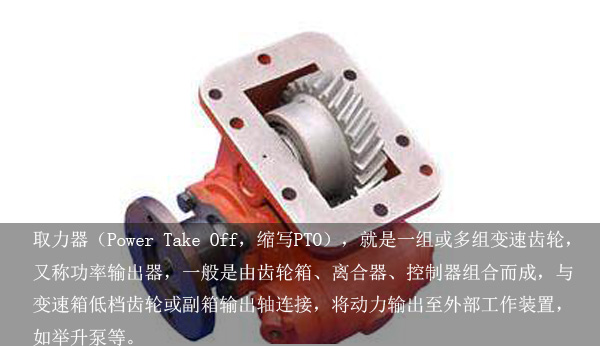
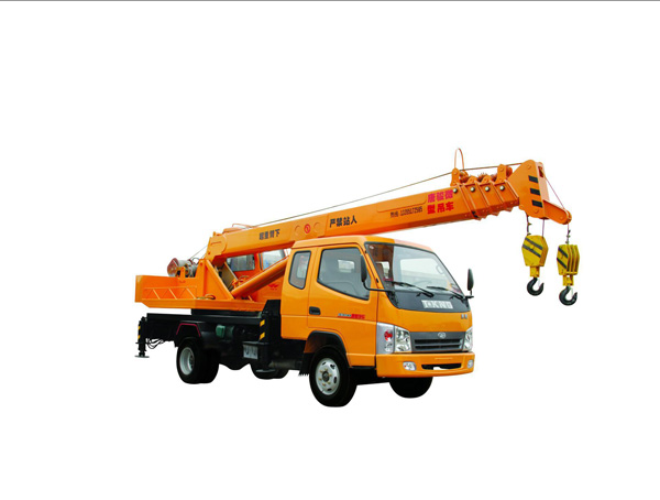
We all know that the necessary components of the crane are the power take-offs. The power take-off is an important part of the small crane. It mainly draws power from the chassis transmission to drive the hydraulic pump, transmits the power of the internal combustion engine of the carrier to the transmission, and then The power take-off is used to take out the power from the intermediate shaft of the transmission, and then the hydraulic pump is driven by a special drive shaft to supply the pressure oil to other components of the crane to complete the lifting operation. In fact, the crane is mainly based on the principle of physical leverage, in a certain range through vertical and horizontal lifting handling heavy objects. Generally, it is mainly used for lifting relatively heavy articles, and sometimes it is also possible to hoist loose materials and liquid materials with suitable spreaders. The work of the crane is generally characterized by intermittent movements, that is, in the state of a work cycle, the materials are taken, transported, unloaded, and the like in order to perform alternate work. Each institution is often in the starting, braking, and working directions. The power take-off device is generally connected with a transmission shaft or directly connected with a gear pump and completes the lifting work in combination with other components. The working principle of the power take-off of the crane (operation method): 1. After the internal combustion engine is started, the power take-off control device first needs to run at low speed for a period of time. After the temperature of the internal combustion engine and the pressure of the lubricating oil are normal, the power take-off device can be operated together with the remaining components. When it is necessary to drive the hydraulic pump, it is necessary to close the power switch of the power take-off and then depress the clutch pedal. When the power indicator light 12 is lighted, it indicates that the hydraulic pump has started working. At this point, the speed of the hydraulic pump can only be controlled by the on-board cab. At this time, getting off the accelerator pedal will not have any effect. When it is necessary to stop the work of the hydraulic pump, it is necessary to step on the clutch pedal in the getting off cab, and then turn the variable power take off switch to the off position. When the power indicator light goes out, the off accelerator pedal will resume control of the engine speed. The function of the crane can be transferred. 2. Manually operated power take-offs are mainly used on wheeled cranes. Power take-offs are bolted to the power take-off window of the crane's transmission. It is mainly through a three-axle gearbox through the large gear on the active tower gear. Mesh with the power output gear of the transmission's countershaft. The power of the engine is mainly input through the active tower gear, and then it is transmitted through the gears on the intermediate shaft and the main shaft. Finally, it is output by the connecting flange on the main shaft. Finally, the universal drive shaft drives the hydraulic pump. Use the shift lever to toggle the shift fork shaft to move the sliding tower gear to complete the in-gear (combination) and the off-gear (disengagement). When the crane is running, the hydraulic pump must be disconnected from the engine. Combined control of power take-off, and some use of rods in the cab to operate, that is, manual gear and pick off; most use electromagnetic control power take-off gear, pick off. At present, most domestic power take-off devices are used on dump trucks, so the requirements for power take-off devices are relatively single. In Europe, North America and other countries, due to the relatively high requirements for power take-offs of special vehicles, manufacturers of power takeoffs will design multi-output power take-off devices or power take-off devices with clutches to increase the multi-functional operation of cranes. . I hope the above article is helpful to you! More related content You can follow our official website. Welded Neck Flange (WN) Raised Face (RF) material including CS A105, A105N, A350 F2; SS A182 F304, F304L, F316, F316L, F321, F347; AS A182 F11, F22... Weld Neck Flange,Asme B16.5,WN Flange,Raised Face Weld Neck Flange, A105 WN Flange Shijiazhuang Bang dong Pipeline Technology Co,Ltd. , https://www.bd-pipefitting.com

Raised Face, Flat Face, Ring Type Joint Face are available.
Other Type of Flanges as following: Slip on , Threaded , Blind , Socket Weld , Lap Jont , Orifice , Spectacle Blind Flange, Spade & Spacer and other flanges.
Welded Neck Flange (WN) Raised Face (RF) Specification:
Name: Welded Neck Flange (WN) Raised Face (RF)
Face Type: RTJ, RF, FF
Material: Carbon Steel: ASTM A105/N, ASTM A516 GR60/65/70...
Stainless Steel: ASTM A182 F304/L, 316/L, 321,347...
Alloy Steel: ASTM A182F11, F22...
Standard: ASME B 16.5 /ANSI B 16.5; ASME B 16.47 SERIES A/SERIES B; BS4504; EN1092...
Brand: BD
Packing: Wooden case or pallet