Fixed tube heat exchanger consists of tube bundle, tube plate, shell, head, folded plate, etc. Tube bundle ends fixed in the tube plate, the tube can be expanded (the inner hole of the tube with mechanical expansion, so that the tube wall from the inward to outward extrusion and fixed in the tube plate) or welded to the tube plate. The tube bundle is placed within the tube shell, with headers and flanges fixed at both ends. In this way, one fluid flows from the inside of the tube and the other from the outside. The space between the two heads and the tube plate is used to distribute or collect the fluids inside the tube. The two fluids do not mix with each other, but only exchange heat through the tube wall.
Advantages: simple and compact structure, high pressure resistance, low cost and easy to clean the tube side.
Disadvantages: Risk of blockage when the tube is damaged or needs to be replaced.
When the difference between the wall temperature of the tube bundle and the shell or the coefficient of linear expansion of the material is large, a large thermal stress will be generated in the shell and the tube bundle. A flexible compensation ring (also called expansion joint) should be installed on the shell to reduce the thermal stress.
Fixed Tube Heat Exchanger,Tubular Exchanger,Tema Heat Exchanger,Fixed Tube Sheet Heat Exchanger Guangdong Jiema Energy Saving Technology Co.,Ltd , https://www.jmheatexchanger.com
Main Specifications
Below is our standard tube mills table, we can customize machines as per customer special requirements
Model
Round Pipe
Square Pipe
Rectangular Pipe
ThicknessÂ
 Pipe Length
Line Speed
 Welding Type
High Frequency Power/KW
 Standard
TG16
7.5 - 16 mm
/
/
0. 4 - 1.0 mm
4.0 - 10.0 meters
Max. 120 m/min
Solid State High Frequency Welding
60
/
TG20
10 - 25.4 mm
 10 x 10 - 20 x 20 mm
 10 x 20 - 10 x 30 mm
0.4 - 1.0 mm
4.0 - 10.0 meters
Max. 120 m/min
Solid State High Frequency Welding
60
/
TG32
12.7 - 38.1 mm
 10 x 10 - 30 x 30 mm
 10 x 20 - 40 x 20 mm
0. 5 - 1.8 mm
4.0 - 10.0 meters
Max. 120 m/min
Solid State High Frequency Welding
100
/
TG45
15.0 - 50.8 mm
 12 x 12 - 40 x 40 mm
 10 x 20 - 50 x 30 mm
0.6 - 2.0 mm
4.0 - 10.0 meters
Max. 100 m/min
Solid State High Frequency Welding
150
/
TG50
20.0 - 63.5 mm
 15 x 15 - 50 x 50 mm
 10 x 20 - 60 x 40 mm
0.8 - 2.75 mm
4.0 - 10.0 meters
Max. 100 m/min
Solid State High Frequency Welding
200
/
TG60
25.4 - 76.4 mm
 20 x 20 - 60 x 60 mm
 10 x 30 - 80 x 40 mm
1.0 - 3.0 mm
4.0 - 10.0 meters
Max. 90 m/min
Solid State High Frequency Welding
250
/
TG76
 31.8 - 89.0 mm
 25 x 25 - 70 x 70 mm
 20 x 30 - 100 x 40 mm
1.0 - 3.75 mm
4.0 - 10.0 meters
Max. 80 m/min
Solid State High Frequency Welding
300
/
TG89
38.1 - 102.0 mm
 30 x 30 - 80 x 80 mm
 20 x 40 - 100 x 60 mm
1.0 - 4.0 mm
4.0 - 10.0 meters
Max. 80 m/min
Solid State High Frequency Welding
300
/
TG114
38.1 - 114.3 mm
 30 x 30 - 90 x 90 mm
 20 x 40 - 60 x 120 mm
1.0 - 4.0 mm
4.0 - 10.0 meters
Max. 70 m/min
Solid State High Frequency Welding
300
/
TG125
63.5 - 127 mm
 50 x 50 - 100 x 100 mm
 60 x 40 - 150 x 50 mm
2.0 - 5.0 mm
4.0 - 10.0 meters
Max. 60 m/min
Solid State High Frequency Welding
400
/
TG165
76. 2 - 165 mm
 60 x 60 - 130 x 130 mm
 80 x 40 - 140 x 120 mm
2.0 - 6.0 mm
4.0 - 10.0 meters
Max. 60 m/min
Solid State High Frequency Welding
500
/
TG219
89.0 - 219.0 mm
 70 x 70 - 170 x 170 mm
 80 x 60 - 140 x 200 mm
2.0 - 8.0 mm
4.0 - 10.0 meters
Max. 60 m/min
Solid State High Frequency Welding
600
/
API&ERW 168
76.2 - 168.0 mm
60x60 - 130x130Â mm
80x40 - 150x100Â mm
2.0 - 8.5 mm
5.0 - 12.0 meters
Max 60Â m/min
Solid State High Frequency Welding
600kw
API 5LX, API 5L A&B, ASTM A53 A&B, up to API X-70
API&ERW 219
89.0 - 219.0 mm
70x70 - 170x170Â mm
80x60 - 200x140Â mm
 3.0 - 10.0 mm
5.0 - 12.0 meters
Max 55Â m/min
Solid State High Frequency Welding
800kw
API&ERW 325
114.0 - 325.0 mm
 90x90mm - 250x250 mm
 80x100- 200x300 mm
4.0 - 12.5 mm
5.0 - 12.0 meters
Max 40Â m/min
Solid State High Frequency Welding
1000kw
API&ERW 508
165.0 - 508.0 mm
130x130 - 400x400Â mm
120x140 - 350x450Â mm
6.0- 12.7 mm
5.0 - 18.0 meters
Max. 30Â m/min
Solid State High Frequency Welding
1000kw

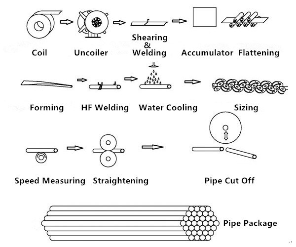
Flow Chart
Step1: Uncoiler
Uncoiler the function is to support and expand the strip, so strip can enter into machine to roll forming. Strip can be expanded by hydraulic or pneumatic and uncoiler can be rotated 180 degree. Strip expand speed can be adjusted, braking device designed with pneumatic or hydraulic cylinder to press the brake rubber block
Step2: Shear & end welding
It is used to shear the head and the end of the steel strip of two steel coils, cutting off the irregular part then welding two steel strips, so machine can work continuously. Â
Step3: Accumulator
Installed between shear & end welder and forming mill, horizontal spiral accumulator store a large amount of strip in a reasonable footprint space to give enough time for shear & end welder to cut and join the ends of two successive coils with non-stop tube mill
It has vertical cage type accumulator for small size tube mill
Step4: Forming
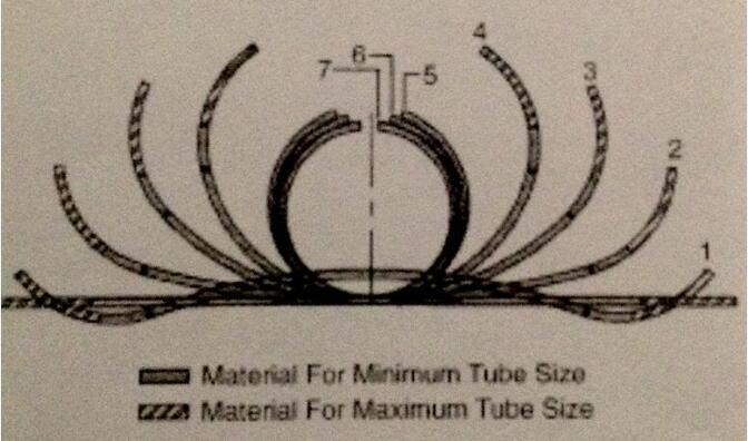
The function of this part is to make the steel strip become to the tube blank by forming rollers
Step5: welding & scarfing
The function of this part is to center the welding seam and guide the tube blank to welding device, so the welding seam will be closed before welding, use scarfing tool to remove the burr to ensure the smooth welding
Step6: Sizing
The function of this part is used to finish the tube blank from the forming machine, so the tube size can meet the physical dimension as customer required, form to square and rectangular and other shape profiles
Step7: Straightening
4 rolls turk head straightening, straighten pipe online to achieve the ideal flatness
Step8: Cut off saw
Cut off the pipe with required length, length of pipe can be set
With option of cold saw and flying saw
Step9: Run out table
This unit is to convey the finished pipe to packing, pipe transmit by dynamic roll. A signal sensing device installed in the end of run out table, when pipe touch the signal sensing device, it will feedback the signal to control panel, control panel start working and discharge the pipe
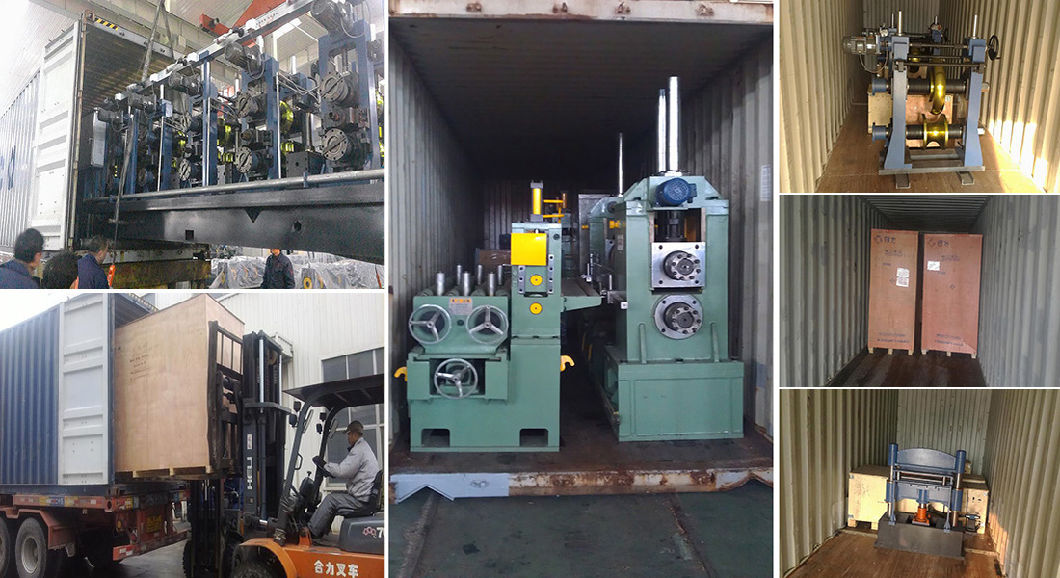
Packing & Delivery
Not only the Good Machine, but also the Most Attentive Service
Integrity Solution & Turnkey Project
Creat the Value of Steel
Â
Slited coil is uncoiled and feed into forming section passing through the equipment of entry section. Entry section enables tube mill to run continuously by using strip joining and accumulator. Before welding, pipe is formed in round shape passing through a series of driven and idler rollers of forming section. In welding section pipe is longitudinally welded by using high frequency induction welding method. Outside bead is removed and formed in shape of scrap. The weld seam is ironed and pipe passes through the cooling section. Then in sizing section, pipe is formed to specified size and converted into specified shape. After sizing, pipe is cut to required length by using flying saw cut off equipment and delivered to collecting table after passing through run out conveyor.
Main Specifications
Below is our standard tube mills table, we can customize machines as per customer special requirements
Model
Round Pipe
Square Pipe
Rectangular Pipe
ThicknessÂ
 Pipe Length
Line Speed
 Welding Type
High Frequency Power/KW
 Standard
TG16
7.5 - 16 mm
/
/
0. 4 - 1.0 mm
4.0 - 10.0 meters
Max. 120 m/min
Solid State High Frequency Welding
60
/
TG20
10 - 25.4 mm
 10 x 10 - 20 x 20 mm
 10 x 20 - 10 x 30 mm
0.4 - 1.0 mm
4.0 - 10.0 meters
Max. 120 m/min
Solid State High Frequency Welding
60
/
TG32
12.7 - 38.1 mm
 10 x 10 - 30 x 30 mm
 10 x 20 - 40 x 20 mm
Model NO.: TG125
Line Speed: Please Check Below
Thickness: Please Check Below
Trademark: TGMCO
Transport Package: Wood Box
Origin: China
HS Code: 8515219100
Model NO.: TG125
Line Speed: Please Check Below
Thickness: Please Check Below
Trademark: TGMCO
Transport Package: Wood Box
Origin: China
HS Code: 8515219100
Slited coil is uncoiled and feed into forming section passing through the equipment of entry section. Entry section enables tube mill to run continuously by using strip joining and accumulator. Before welding, pipe is formed in round shape passing through a series of driven and idler rollers of forming section. In welding section pipe is longitudinally welded by using high frequency induction welding method. Outside bead is removed and formed in shape of scrap. The weld seam is ironed and pipe passes through the cooling section. Then in sizing section, pipe is formed to specified size and converted into specified shape. After sizing, pipe is cut to required length by using flying saw cut off equipment and delivered to collecting table after passing through run out conveyor.