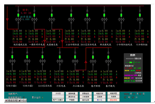
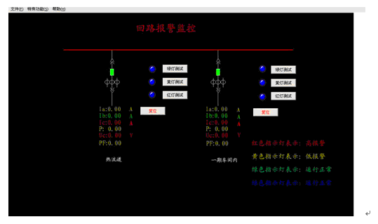
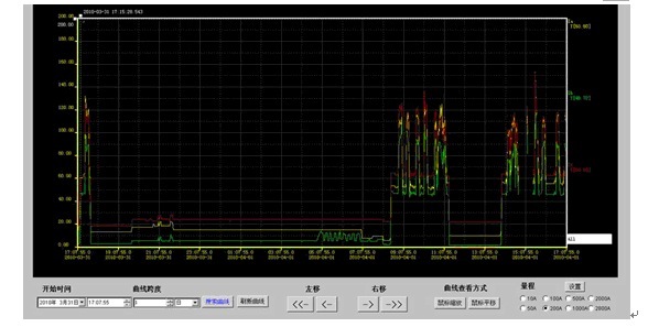
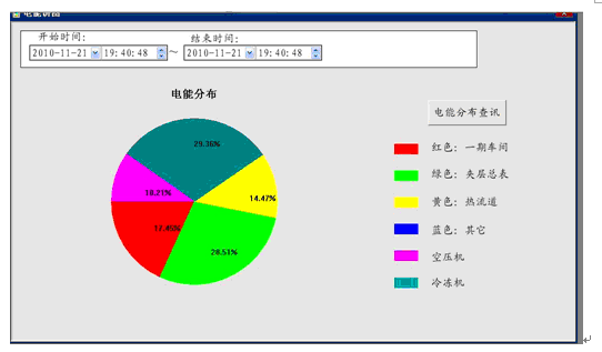
Xu Shuang Ankerui Electric Co., Ltd., Shanghai Jiading 201801 I. Analysis of power consumption characteristics of users in the industry The electrical equipment industry can be subdivided according to the national production industry: motor manufacturing (generator manufacturing, motor manufacturing, micro-motor and other motor manufacturing); transmission and distribution and control equipment manufacturing (transformer, rectifier and inductor manufacturing, capacitors and their matching Equipment manufacturing); wire, cable, optical cable and electrical equipment manufacturing (wire and cable manufacturing, optical fiber, fiber optic cable manufacturing), etc., mainly engaged in electrical machine manufacturing industry. The electrical equipment industry has a wide range of product applications and is entering various areas of the national economy and people's lives. The industry is divided into large-scale and small- and medium-sized enterprises according to transformer capacity. Large-scale enterprises adopt dual-supply power supply mode. Small and medium-sized enterprises generally use single-supply power supply. Users usually have production time from 8:00 to 17:00, and they also have continuous production for 24 hours. For the daytime peak production and low valley load difference, it is a typical “middle size, two small,†and its load curve for continuous production is relatively stable, generally a difference of about 20%. During the high temperature or cold season, the electricity demand of these enterprises has also changed. With the change of temperature, the electricity load will increase significantly. From the perspective of the whole year, these enterprises exhibited the characteristics of “high summer and winter loads, and small loads in spring and autumnâ€. Due to the wide range of products in the electrical equipment industry, the requirements for process standards, environmental controls, etc. of such enterprises are not the same. The main electrical equipment is shown in the following table: Electric equipment manufacturing industry equipment classification category Major equipment Note Non-productive load Canteen, lighting, computer printers and other office appliances, air conditioning, spray, repair general Auxiliary production load Punch, stamping, welding, copper and aluminum welding, machine tools, milling machines, compressors, booster, crane, lathe, chiller, drying room, injection molding machine, heat treatment, tempering furnace, box furnace, electric boiler, cable machine general The main productive load Pipeline (multiple) important Safeguarding load Fire-fighting equipment, security lighting important II. Analysis of Industry Users' Participation in Peak Dislocation and Power Limiting Capability 1. The electricity load in the industry has a large impact on the time, season, and climate. Its load curve shows “middle and small†during the day, while the annual load curve shows the characteristics of “high load in summer and winter and small load in spring and autumnâ€. . When there is a gap in the grid load, according to the characteristics of its load, load control is performed step-by-step, and the technical peak is implemented according to the principle of first controlling the non-production load and then controlling the production load, the first general load and then the important load. 2. Emergency peak load limiting when the load can be turned up and down quickly, without causing personal and major equipment damage, such as lighting, air conditioning, office equipment, punching, stamping, welding, copper and aluminum welding, machine tools, milling machines, Compressors, boosters, lathes and other equipment. Some important loads, such as firefighting equipment, are not suitable for quickly avoiding peaks. 3. The user's phase-shifting in the industry can be carried out through internal control measures, adjustment of commute time, arrangement of partial equipment overhaul, and arrangement of high-temperature leave. For example, green lighting technology, stop punching, stamping, welding, copper-aluminum welding and other equipment can be used through internal control measures. For example, the main electricity equipment can be used during the low-hour period when adjusting the commute time. Avoid the sudden increase in electricity load caused by commute at work and reduce the situation. If some equipment is used for overhauling, equipment such as production lines can be arranged for maintenance during peak hours. Third, the industry users involved in the peak load limitation technology program (I) Gap Level IV Participation Plan 1. Staged peak shift: After receiving the peak load, we stopped the logistic facilities. 2. Emergency peak shift: Taking into account the small grid load gap, during 8:30 to 11:30, 13:00 to 16:00, and 16:00 to 22:00 during peak hours, lighting, computer printers and other office appliances, air conditioning, spray, Non-productive loads such as repairs; stop the cafeteria from 10:30 to 11:30; disable punching, stamping, welding during 8:30 to 11:30, 13:00 to 16:00, and 16:00 to 22:00. , copper and aluminum welding, machine tools, milling machines, compressors, superchargers, cranes, lathes, chillers, drying rooms and other auxiliary production load. (II) Gap Level III Participation Plan 1. Staged peak shift: After receiving the peak load, it stopped the logistic power supply and auxiliary production facilities. 2. Emergency peak shift: With the gradual increase of the grid gap, based on the implementation of the IV-grade plan, the injection molding machine will be stopped at 8:30 to 11:30, 13:00 to 16:00, and 16:00 to 22:00 during the electricity use. Heat treatment, tempering furnace, box furnace, electric boiler, cabling machine and other auxiliary production load. (III) Level II Participation Scheme for Gap 1. Staged peak shift: After receiving the peak-to-peak indicator, it stopped the logistic power supply, auxiliary production facilities and half of the production lines or arranged for half equipment maintenance. 2. Emergency peak shift: With further increase of the grid gap, when the contradiction between supply and demand is significant, based on the implementation of the level III program, during the period of 8:30 to 11:30, 13:00 to 16:00, and 16:00 to 22:00, Increase the number of major production loads such as two production lines and two production lines. (IV) Gap Level I Participation Plan 1. Staged peak shift: After receiving the peak-to-peak indicators, it stopped the logistic power supply, auxiliary production facilities and all production lines, arranged equipment maintenance or put high temperature (frigid cold) leave. 2. Emergency peak shift: With the further increase of the grid gap, when the contradiction between supply and demand cannot be balanced, based on the implementation of the Level II program, electricity is used at 8:30 to 11:30, 13:00 to 16:00, and 16:00 to 22:00. During the period, all power facilities, including the other two lines and two production lines, will be stopped except for the security load. Fourth, the industry users involved in the peak load shifting risk and precautions 1. In the event of a sudden power outage, the traffic during work will lose its balance and will be tilted or shed. The body itself may be damaged or scrapped. Ground facilities and operators may also be injured, causing damage and casualties. 2. Some equipment and facilities in high-precision numerical control equipment, sudden power failure will cause system data loss, product scrap, equipment serious damage, restore normal production takes a long time, resulting in major economic damage. 3. In the event of a sudden power outage of equipment such as melting furnaces, high-frequency furnaces, boilers, etc., the furnace will be scrapped, the molten metal solution will be scrapped, and there will be hidden dangers of fire. Therefore, when the industry participates in the peak of change, enterprises should, according to their own actual conditions, formulate internal emergency plans scientifically and reasonably, actively cooperate with the peak implementation, eliminate the occurrence of malignant accidents, and minimize losses. V. Functions and Applications of Intelligent Power Monitoring An electrical manufacturing company needs to make a more elaborate budget and management of the energy consumption of the entire plant, and it can realize the measurement display of electrical power parameters and the measurement of electrical energy, and the current limit alarm (a three-layer red, yellow, and green signal display is used at the site). The site uses Acrel-3000 power management system with ACR series management instruments to realize remote electric parameters (current, voltage, power, power factor, etc.) real-time monitoring and classification of energy metering. The maximum demand (MD) measured in the field is compared with the preset limit of the system, and the alarm is given when the quantity exceeds the limit. 5.1 Network Structure Topology The entire system adopts a network distributed structure. The monitoring host is located in the environmental quality inspection department on the second floor of the office building. The data acquisition is mainly divided into three zones: the loop equipment for washing machines, the loop circuit for refrigerator production, and the loop circuit for old factory air conditioners. The communication of the power meter is 485 bus structure, the signal is transmitted to the data collector through the shielded twisted pair, and the data collector is connected to the local area network of the plant. 5.2 System Functions 1) System main interface The system provides simple, easy to use, and good user interface. Using Chinese interface, CAD graphic shows the primary electrical wiring diagram of the electrical distribution system, shows the status of the electrical distribution system equipment and the corresponding real-time operating parameters, the screen timing switching tour; dynamic refresh of the screen real-time; analog display; switch display; continuous recording The display, etc., can be seen by the changes in the screen colors (red indicates the closing state and green indicates the opening state). Log in as an ordinary user, and through the operation of the main interface, you can view the electrical parameters (current, voltage, active, reactive, power factor, and power) of each loop. If you log in to the highest authority user, you can realize the internal power report and current of the system. Curve, alarm information printing and exporting function. 2) System remote signaling alarm When an operating fault occurs in the system, an audible and visual alarm will be promptly issued to prompt the user to respond to the fault circuit in a timely manner. At the same time, the time and loop name of the event are recorded automatically so that the user can query and remember the cause of the fault. 3) Trend curve analysis Acrel-3000 power management system provides analysis interface of real-time curve and historical trend curve, and analyzes the current load running status of the circuit by calling the relevant circuit real-time curve interface. For example, by invoking the real-time curve of a given circuit, the signal fluctuation caused by the electrical equipment of the circuit can be analyzed. The historical trend of the system is that the system can view its historical trend for all stored data and facilitate the quality analysis of the monitored distribution network by the engineering personnel. 4) Report statistics The energy report is divided into three kinds of reports: time report, daily report and monthly report. Select the date to be queried to display the power consumption for each time period, and display the report comparison histogram for electricity consumption in each time period to facilitate the administrator to view the analysis. 5) Energy Pie Chart You can view the percentage of electrical energy in different loops at any time to facilitate the adjustment of the company's internal energy consumption. 1) Real-time performance: Before the implementation of the project, the on-site data is mainly reproduced manually, which is 2 times a day. The time of each loop is not uniform, and it can be of poor quality. After the project is implemented, it is collected in real time in the background, and once in 50mS, the comparability is strong. 2) Storage management: paper records before the project implementation, turn over the containers when inquiries, long-term volatility, data date management is complex; the computer storage after the implementation of the project, the data can be stored for more than 10 years, the query speed, just a mouse, quickly and accurately . 3) Overall analysis: Before the implementation of the project, the electricity consumption in each period and the power consumption of each loop cannot be compared horizontally and vertically. After the implementation of the project, the curve analysis is performed. The peak-to-valley period is obviously contrasted, and it is easy to cut peaks and valleys, and three-phase electricity is used. The deployment is relatively balanced. 4) Data security: Decentralized management before project implementation, manual scheduled backup, inaccurate backup of continuous data, centralized management after project implementation, automatic back-up of the system. Equipment management: Before the implementation of the project, each drawer cabinet circuit should be turned on and off at the scene, and there should be no alarm when the power is off. After the project is implemented, it is clearly displayed through a system diagram at the backstage. When the circuit is tripped, it is automatically recorded in the background and is accompanied by an automatic alarm. 5) Load adjustment: Before the implementation of the project, it is difficult to adjust the balance of the three-phase loop load; after the project is implemented, the currents of each loop are distributed and managed in real time so that the three-phase current is balanced and the log is recorded. Sixth, the main monitoring products (1) ACR330ELH meter for high voltage circuit or low voltage circuit The meter is a power quality analyzer. The main functions are: LCD display, all-electric parameter measurement (U, I, P, Q, PF, F, S); four-quadrant energy metering, multi-rate energy statistics; THDu, THDi, 2-31 times each harmonic wave component; Voltage crest factor, telephone waveform factor, current K factor, voltage and current unbalance degree calculation; Grid voltage and current positive, negative, zero sequence component (including negative sequence current) measurement; 4DI+ 3DO (DO3 overvoltage, undervoltage, overcurrent, unbalance alarm); RS485 communication interface, Modbus protocol or DL/T645 protocol. Dimensions: 120 × 120mm, opening size: 108 × 108mm. Suitable for high pressure important circuit or low voltage inlet cabinet. (2) ACR220EL power meter with low voltage contact or outlet loop The main functions of the table are: LCD display, all-electric parameter measurement (U, I, P, Q, PF, F); four-quadrant energy metering, multi-rate energy statistics, maximum demand statistics; 4DI+2DO; RS485 communication interface , Modbus protocol. Dimensions: 96 x 96mm, opening size: 88 x 88mm. Suitable for low-voltage connection cabinets and outlet cabinets. (3) Low voltage outlet cabinet selection ARD series The meter measures protection functions such as three-phase current, fixed value query, fixed value setting, overload, phase failure (unbalance), locked rotor, underload, external fault, blocking, undervoltage, 8DI+4DO, power management, and leakage protection , SOE records, a variety of start mode, RS485 communication interface, MODbus protocol / Profibus-DP protocol optional. (4) Energy-saving product optional rail table or APF active filter device Lighting box DDSF1352 meter main functions: current specification 1.5 (6) A, 5 (20) A, 10 (40) A, 20 (80) A optional, multi-rate energy statistics, energy pulse output, RS485 communication interface, Modbus Protocol or DL/T 645 protocol optional. Dimensions: 76 x 89 x 74mm, 4 modules. Suitable for lighting box current, voltage measurement; single-phase energy metering. ARD DTSF1352 rail meter main functions: current specification 1.5 (6) A, 5 (20) A, 10 (40) A, 20 (80) A optional, multi-rate energy statistics, energy pulse output, RS485 communication interface, Modbus Protocol or DL/T 645 protocol optional. Dimensions: 126 × 89 × 74mm, 7 modulus. Three-phase energy metering for lighting boxes. DTSD1352 rail type meter main functions: LCD display, all-electric parameter measurement (U, I, P, Q, PF, F, S); four-quadrant energy metering, multi-rate energy statistics, maximum demand statistics; current specification 1.5 ( 6) A, 5 (20) A, 10 (40) A, 20 (80) A optional, RS485 communication interface, Modbus protocol or DL/T 645 protocol optional. Dimensions: 126 × 89 × 74mm, 7 modulus. Suitable for power cabinets. ANAPF series active power filter devices are connected to the power grid in parallel and detect harmonics and reactive components of the load in real time. PWM inverter technology is used to generate one current harmonic component and reactive component from the converter. The inversion component is injected into the power system in real time, so that harmonic control and reactive power compensation are realized. Seven, equipment list No. name Model, specification unit Quantity Note 1 Power Meter Three-phase multi-function management instrument ACR230ELH only 10 Ankerui Three-phase multi-function management instrument ACR120EL only 86 Ankerui 2 Monitoring Center duty room Console YT-341 set 1 Xianghe Workstation host IPC-610L/769VG/E5300/2G/500G/DVD/88 Mini Key+Mouse (Original Machine Standard) 2 Serial Ports station 1 Advantech monitor L197WA station 1 Lenovo UPS power supply C1K/1KVA station 1 SANTAK printer HP 1108 A4 format station 1 HP A system software Genuine Microsoft WINDOWS XP/SP3 set 1 Microsoft A Industrial network switch D-LINK 16 ports station 1 D-LINK Industrial Serial Server NPORT5232I RS485 interface × 2 with light isolation station 4 MOXA Industrial switching power supply KDYA-DG30-24K only 4 Huali Power Management Software System Configuration Software Acrel-3000V6 set 1 Ankerui Power Management Software Data Storage Software Acrel-dbSQL set 1 Ankerui Power Management Software Energy Management Software Acrel-EnerSys set 1 Ankerui Power Management Software Device Driver Software Acrel-Driver set 1 Ankerui Photoelectric converter Single mode photoelectric conversion HTB-1100S(25km) only 8 3 Engineering Materials Communication cable Single-mode 4-core fiber km 2 Communication cable Shielded twisted pair RVVSP 2*0.75 km 0.2 Sail Communication cable BVR 1.5mm km 4 Engineering materials Towboards, conversion lines, lines, signs, etc. set 1 Measuring box A total of 4 units are required to be installed in each substation. only 4 Fiber Optic Accessories Includes welding, pigtails, flanges, jumpers, etc. set 4 4 Construction and commissioning Communication cable laying Meter 2200 Comprehensive debugging People/day 25 Equipment transportation costs item 1 training fees item 1 Construction renovation costs item 1 references: [1] Ankerui Electric Co., Ltd. System Solution, 2013.1. [2] Electrical equipment manufacturing industry peak power limit technical guidance. About the Author: Xu Shuang, female, undergraduate, Ankerui Electric Co., Ltd., the main research direction for the smart grid power distribution, Email: Mobile QQ Tungsten carbide welding bars are commonly used in the oil and gas industry for various applications. These bars are made from a combination of tungsten and carbon, which results in a very hard and wear-resistant material. Here are some specific uses of tungsten carbide welding bars in the oil and gas industry: Welding Bar,Ni Based Welding Bar,Ni Based Ctc Welding Bar,Sctc Ni Based Welding Bar Luoyang Golden Egret Geotools Co., Ltd , https://www.xtcalloypowder.com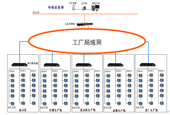

1. Hardfacing: Tungsten carbide welding bars are used for hardfacing applications, where a wear-resistant layer is applied to drilling tools, valves, pumps, and other equipment exposed to abrasive environments. This helps to extend the lifespan of the components and reduce maintenance costs.
2. Drill bits: Tungsten carbide welding bars are used to manufacture drill bits for oil and gas exploration. The hard and durable nature of tungsten carbide makes it ideal for drilling through tough rock formations.
3. Wear plates and liners: Tungsten carbide welding bars are used to create wear plates and liners for equipment used in oil and gas production. These plates and liners protect the underlying metal surfaces from abrasion and corrosion, ensuring the longevity of the equipment.
4. Valve seats and seals: Tungsten carbide welding bars are used to manufacture valve seats and seals for oil and gas valves. The high hardness and wear resistance of tungsten carbide ensure reliable sealing and prevent leakage in critical applications.
5. Downhole tools: Tungsten carbide welding bars are used in the manufacturing of downhole tools such as stabilizers, reamers, and drill collars. These tools are subjected to high pressures, temperatures, and abrasive conditions, and tungsten carbide helps to enhance their durability and performance.
Overall, tungsten carbide welding bars play a crucial role in the oil and gas industry by providing wear resistance, hardness, and durability to various components and equipment.